In the first part of this series, we learned how to program the F18A using the AmpArcade library. We looked at loading the library, initializing the video hardware, and changing the backdrop color. While a good first step, that’s hardly interesting. In this part, we program the tile layer. The tile layer is versatile and useful for many applications, such as text and game backgrounds.
Get a disk image here with AmpArcade and several tile layers examples.
Layers
First, we must detour and understand more about how the F18A and the original VDP organize the video screen.
The VDP divides the video screen into layers or planes. The software may modify each layer independently, and the hardware combines the layers to produce the final on-screen image. This concept is similar to layers in Photoshop or Gimp, and the design makes common animation simple. The background and various objects, such as a space ship or asteroid image, reside on separate layers, and the software may move objects around without needing to save/restore the background or overlapping objects. The layers have an ordering so that a higher layer will obscure a lower layer.
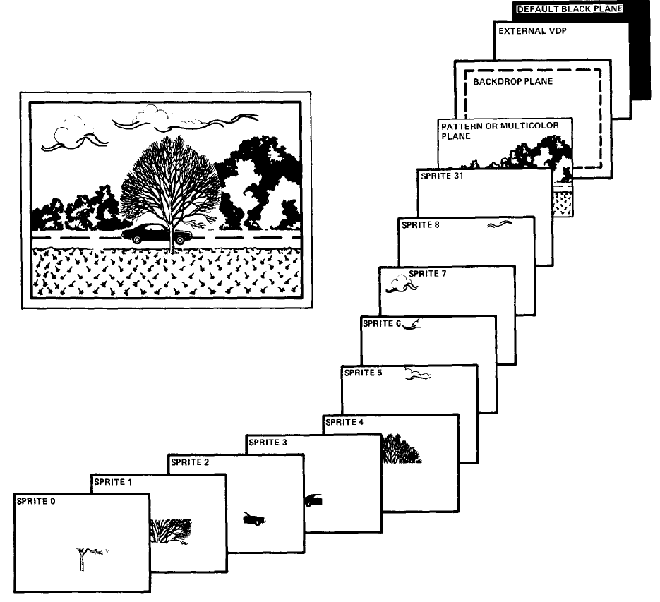
VDP layers diagram from the “Video Display Processor Programmer’s Guide”
The VDP provides these layers:
- Background layer – A solid color that appears only when the higher layers don’t block it
- Tile layer (also known as the “pattern layer”) – Small images arranged in a grid useful for text (if each image is a character) or a background
- Sprite layers (32) – Small animated objects, such as game characters, that move independently over the tile layer
The F18A extends the original TMS9918A with more layers:
- Backdrop layer
- Tile layer 1
- Tile layer 2 – Another tile layer useful for parallax effects or fixed elements, such as score information
- Bitmap layer – A bitmapped image that optionally appears above or below the sprite layer
- Sprite layers (32)
The F18A also introduces additional capabilities to the layers, including more colors, scrolling, and more capable sprites. For this discussion, we limit ourselves to the capabilities of the original VDP since AmpArcade does not support the expanded capabilities of the F18A.
The Tile Layer
The tile layer, sometimes also known as the pattern layer, divides the screen into a rectangular grid. Each grid square, called a tile, contains a pattern of pixels. In Graphics Mode I (GM1), the grid of tiles has 32 columns and 24 rows, and each tile may contain one of 256 different 8×8 pixel patterns. Other modes are slightly different, and this post only describes GM1. This “Programmer’s Guide” from Texas Instruments details each video mode.
If the patterns look like letters and numbers, the tile layer is perfect for displaying text. Unlike the Apple II text mode where the available characters are factory-determined in ROM, the character set for the tile layer is up to the programmer. Want a different font? Want bold or italic? Foreign language characters? Symbols? Emojis? Line-drawing characters like MouseText? No problem. You may design your own characters.
However, patterns do not need to be recognizable characters. The patterns could be elements of a game background or graphic. You may subdivide complex graphics into multiple patterns. For example, if you want a letter that is double-high, you may create two patterns, one with the top of the letter and another with the bottom. Or, if you need a gun turret for a game, you may subdivide the turret image into as many patterns as needed. Don’t underestimate this capability; look at many excellent games, and you’ll notice backgrounds with repeating tiles.
Internally, the VDP uses three tables to define the contents of the tile layer. The “pattern table” describes up to 256 reusable 8×8 patterns. The “color table” describes the colors of the patterns. The color table only allows two different colors for every eight patterns, and the table contains 32 bytes (256 patterns divided by 8, with two colors packed into one byte). The “name table” describes the pattern visible in each tile, and the table consists of 768 bytes (32 columns times 24 rows). The table sizes vary with graphics mode, and these numbers only apply to GM1; however, the basic table structure applies to all modes.
Let’s try programming the tile layer. Refer to my first part to load AmpArcade, then initialize GM1:
REM Initialize Graphics Mode I, memory layout variant A.
&GM1A
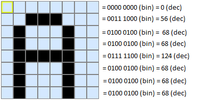 Next, define a tile pattern with the DTIL command. DTIL requires 9 numbers. The first number is the pattern number from 0 to 255. The next eight numbers each range from 0 to 255 and define the pattern of pixels for one row each, beginning with the top-most row. In this example, let’s define pattern #65 as the letter “A”:
&DTIL,65,0,56,68,68,124,68,68,68
DTIL only defines the patterns, and an additional command is necessary to set a tile to a pattern. Typically, the programmer defines all of the patterns once and sets tiles to patterns with the STIL command throughout the program. STIL requires 3 numbers. The first number is the column (0-31 for Graphics Mode 1). The second number is the row (0-23). The final number in the pattern:
&STIL,10,20,65
If you’re following along, you might see the letter “A” (pattern 65) in column 10, row 20. I say “might” because we have not specified the colors. If, by chance, the color table chooses identical foreground and background colors for this pattern, you won’t be able to see the pattern.
To set the color, use the CSET (color set) command. This command requires two numbers. The first number is the color group from 0 to 31. Recall that you may only set the color for a group of 8 patterns. To find the color group for a pattern, divide the pattern number by 8 and discard the remainder. For our example above using pattern 65, the color group is 8 (65/8 = 8, discarding the remainder). The second number defines the foreground and background colors for the pattern. Multiply the foreground color by 16 and add the background color to calculate the CSET color number. The following example sets pattern group 8 to foreground color 11 (light yellow) and background color 8 (medium red).
&CSET,8,11*16+8
In addition to the STIL command that sets one tile, AmpArcade provides useful commands for setting multiple tiles:
REM Beginning in column 5 and row 10, set a horizontal row of tiles to patterns 65 and 65.
REM &HTIL,<X>,<Y>,<N1>{,<N?>}
&HTIL,5,10,65,65

REM Beginning in column 15 and row 15, set a horizontal row of 10 tiles all to pattern 65.
REM &HROW,<X>,<Y>,<N>,<REP>
&HROW,15,15,65,10

REM Beginning in column 20 and row 22, set a vertical column of tiles to patterns 65 and 65.
REM &VTIL,<X>,<Y>,<N1>{,<N?>}
&VTIL,20,22,65,65

REM Beginning in column 2 and row 5, set a vertical column of 15 tiles all to pattern 65.
REM &VCOL,<X>,<Y>,<N>,<REP>
&VCOL,2,5,65,15

REM Fill the entire tile layer with pattern 65.
&FILL,65
Loading Patterns
You may define all 256 patterns with 256 separate DTIL commands, but that gets really tedious really fast. It’s possible to store multiple patterns in a single binary file on disk and transfer the data to the VDP. Let’s say you have a file CHAR with patterns for a basic set of letters, numbers, and punctuation. Each pattern is 8 bytes, and the patterns are in order with the first 8 bytes representing pattern 0, the second 8 bytes representing pattern 1, and so on.
This approach employs a new command, LD, to load data into the VDP’s memory. To use LD, you must know something about the layout of the VDP’s memory (VRAM), a topic we’ve avoided so far. The memory layout is configurable and changes with both video mode and configuration details. The GM1A command gives the following memory layout for the tile layer:
- Name Table: addresses 1024 ($400) to 1791 ($6FF)
- Color Table: addresses 1920 ($780) to 1951 ($79F)
- Pattern Table: 2048 ($800) to 4095 ($FFF)
The LD command requires 3 numbers. The first is the source address in the Apple II’s memory. The second is the destination address in the VDP’s memory. The third is the length of the data in bytes.
REM Load the tile layer patterns from disk into the Apple II's memory at address 8192.
REM A complete set of patterns requires 2 KB of memory, but you don't need to define every pattern.
REM The "CHAR" file is only 832 bytes long, which defines 104 patterns (832 bytes/8 bytes per pattern).
REM We could use any available memory location on the Apple II.
BLOAD CHAR,A8192
REM Copy data for 104 patterns (8 bytes each) to VDP memory address 2048, which contains the pattern table.
&LD,8192,2048,104*8

REM Display all patterns.
REM First, set the pattern group colors to a blue foreground and a gray background.
FOR I=0 TO 31 : &CSET,I,4*16+14 : NEXT I
REM Next, show each pattern on screen.
REM Note that CHAR only contains 104 patterns, so some patterns will be whatever garbage was already in VRAM.
FOR Y=0 TO 23 : FOR X=0 TO 31 : &STIL,X,Y,Y*32+X : NEXT X,Y
What’s next?
Try writing a program that uses the CHAR patterns and displays a sentence on the screen. Then, use DTIL to define a new pattern that resembles the Apple logo and draw a red border of Apples around your message. This bootable disk image contains everything you need, including the CHAR file.
In the next part, we’ll look at modern tools to help us create new patterns and tile layouts.